Taking the stress out of engineering Understand article
Darren Hughes from the Institut Laue-Langevin in Grenoble, France takes a look at stress. How can it be manipulated to make safer rails for trains or more efficient wind turbines – and what can we learn from neutron- and X-ray analysis?
We all know the feeling: a hard day, overloaded with work, and you feel stressed. Well, did you know that metals used in the construction of aircraft, buildings, cars and trains get stressed as well? In fact almost everything around us is subject to constant stresses, starting from the day they are made.
In many situations, it is not too important if the stress causes something to fail because the damaged part can easily be replaced. However these stresses become extremely important in safety-critical components, for example in an aircraft engine or on a railway track. The engineers that design and manufacture these components are now working with scientists in Grenoble, France, to understand how these stresses are caused and to improve the component lifetime and reliability.
What is stress?
When a force is applied to an object, the object is said to be experiencing stress. Stress is effectively a measure of an object’s response to a force. We define stress mathematically as the force applied, divided by the area over which it applies. The SI unit of stress is therefore Newtons per metre squared (Nm-2). It is sometimes easy to confuse stress and pressure as the units of pressure are also Nm-2. The important difference is that pressure is the external force on the object whereas stress is an internal force.

natural growth pattern of a
tree causes residual stresses
in the wood of the trunk.
When the trunk is felled and
the wood begins to dry, these
stresses can overcome the
strenght of the wood and
lead to significant cracks
Image courtesy of Darren
Hughes
Stress in metal components is present right from the time of manufacture and arises during their formation. Stress in engineered components is often described in two ways, as either residual or applied. The stress that remains locked in a component after manufacturing is called the residual stress. When the component is used, it is subjected to applied stress, for example a train exerts an applied stress on the rail. The total stress on the component is therefore the sum of the applied and residual stresses.
Of course, stress can either be positive or negative depending upon the nature of the force. If a region of a component is stretched, then the stress is generally positive, or tensile; on the other hand, if it is squeezed then the stress is negative, or compressive. After manufacturing, the residual stresses in a component change each time the component is used, because of the applied stresses. The degree of change depends on the type of wear, the length of use, and the forces applied. Eventually, mechanical wear combines with the stresses and causes the component to fail.
crack
Image courtesy of Darren
Hughes
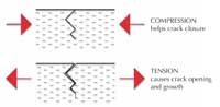
Are all stresses bad or can some be beneficial? Yes, although a tensile stress is generally considered bad, a compressive stress is usually considered beneficial. Imagine a small crack that has formed in a surface (see right). If the stress around the crack is tensile, the crack is pulled apart by the stress and becomes deeper.
On the other hand, if the stress is compressive, then the crack is pushed back together and grows no further. Modern engineers have devised production methods which allow them to put a compressive residual stress into regions of new components where small cracks might develop and thus improve the lifetime and wear resistance of critical components.
Sound simple? One problem is that the whole component has to obey the laws of physics, so that total stress is balanced when it is at rest – this is Newton’s first law of motion. Thus, if you have a region of beneficial compression, there will be a balancing region of harmful tension elsewhere. Engineers therefore need to measure the residual stresses in a metal component so that they can locate both the compressive and tensile stresses, measure their magnitude and then further improve the manufacturing techniques. It is generally quite easy to calculate the applied stresses (e.g. from the way the weight of a train is distributed in the rails) but much more difficult to determine the residual stresses.
Understanding residual stress is increasingly important as structures are required to be stronger, more economical and less environmentally damaging. In the transport sector, the use of lighter materials can reduce fuel costs dramatically, but it is essential that the component life is not shortened.
In France, engineers are working with scientists, using the world-leading neutron and X-ray science facilities in Grenoble to measure residual stress in components. Neutron and X-ray beams are fired at a metal component and the resulting diffraction pattern (see box) provides a map of the residual stress in the component. One of the benefits of this non-destructive method is that neutrons and X-rays can penetrate long distances into metals, so residual stress can be studied without cutting the component into smaller pieces. The choice between neutrons or X-rays depends on the type of metal, the component size and the spatial resolution required.
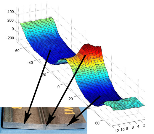
Image courtesy of Darren Hughes
One particularly important area of study is the significant residual stresses induced when materials are joined, for example by welding. The welding process causes thermal mismatch, driving residual stress formation which in turn affects the strength and fatigue life of the weld (see above).
Another important area of investigation is stress in railway rails. The Hatfield train crash in the UK in October 2000 is an example of the extreme consequences that metal failure can have. Four people died and more than 100 were injured when a broken rail derailed a high-speed train. This type of failure in rails is linked to the interaction between small surface cracks and the residual stress in the rail. The image overleaf shows the stress field in the head of a worn rail, measured using X-rays: red zones are tension and blue are compression. The stress pattern is complicated, but regions where the tensile stress approaches the surface of the rail have a greater risk of surface cracks propagating.
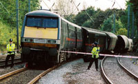
Image courtesy of Rob Welham;
image source: Wikimedia
Commons
Understanding how the residual stresses in a rail change with wear allows engineers not only to develop better rail materials but also to improve maintenance procedures and minimise failures.
Failures arising from stress are not always life-threatening but can nonetheless be a serious problem in many industries. For example, with the growing interest in alternative energy sources, the performance of wind-turbine electricity generators is becoming increasingly important.
The sheer scale of wind turbines combined with the near-constant running in often remote locations – sometimes offshore – poses some difficult engineering questions. In particular, the central bearing of the drive axis (see left) is a key component; with the bearing in contact with the shaft on one side and the rollers on the other, it is exposed to both internal and surface stresses. Conventional surface treatments to create compressive residual stresses on the surface (to minimise surface cracks) have led to unexpected failures, probably due to balancing tensile stresses in other locations.

Image courtesy of Darren Hughes
An ongoing project aims to fully characterise the residual stresses in a complete bearing of 60 cm diameter and 120 kg weight using neutron diffraction. When complete, the project should allow us to modify how the bearing is manufactured and lead to longer service life.
Together, engineers and scientists are working to better understand stress and component failure and ultimately to manufacture long-lasting and safe components. Look on the bright side, not all stress is bad!
Using neutrons and X-rays to study stress
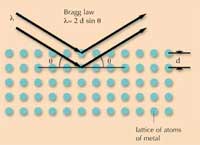
Neutrons and X-rays are used to probe the crystal lattice of atoms in a metal to gain information on the stress state of the component. A beam of neutrons or X-rays with a fixed wavelength (l) is fired at the metal and reflects off at a certain angle. There is a relationship between the spacing of the crystal lattice (d) and the angle at which the beam is reflected (θ). This relationship is called the Bragg law.
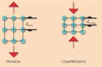
Imagine that you apply a stress – either tension or compression – to the lattice of the metal. When the lattice is stretched, the spacing of the lattice changes. For example, in the case below, dtens is now larger and dcomp is smaller. If we look at the Bragg law again, assuming that the wavelength has not changed, then the angle θ must change. By using a detector to measure the angle at which the beam is reflected, we can work out if the metal is in tension or compression and to what magnitude.
References
- An introduction to the techniques described here can be found in: Withers PJ, Webster PJ (2001) Neutron and synchrotron X-ray strain scanning. Strain 37: 19-33
- Information about neutron facilities at the Institut Laue-Langevin in Grenoble, France: www.ill.fr
- Information about X-ray facilities at the European Synchrotron Radiation Facility in Grenoble: www.esrf.fr
- Both the Institut Laue-Langevin and the European Synchrotron Radiation Facility are members of EIROforum, a collaboration of seven European inter-governmental research organisations, and the publishers of Science in School. See: www.eiroforum.org
Institutions
Review
This article is suitable mainly for pre-university physics students, in particular for the topics of diffraction and properties of matter and materials. It could also be useful for pre-university chemistry students in the context of crystallography. For a more interdisciplinary approach, it could be used to link physics and chemistry with technology and engineering.
The box on neutrons and X-rays could form the basis of a comprehension test. Teachers could ask their students to explain the Bragg law and how a change in tension or in compression affects the diffracted output.
Potential discussion topics include the difference between science and applied science, wave properties (including particle beams as waves), and who bears responsibility for transport accidents. The article also includes some pictures that could be used in lessons.
Eric Deeson, UK