Supporting materials
How to Make a Simple Radiotransmission by Using a Videorecorder and a TV-receiver (Ppt)
Download
Download this article as a PDF
Do you ever get frustrated with that mess of cables connecting your DVD player to your satellite dish, TV and video recorder? Did you know that you can cut those cables – and still get a signal to pass between the machines? Alessandro Iscra, Maria Teresa Quaglini and Giuseppina Rossi from Italy…
Stimulated by the widespread use of modern wireless devices, such as mobile phones, satellite TV receivers and wireless computer networks, many students are interested in the topic of radio transmission. Recognising this interest, we have developed both educational documents and experimentsw1, some of which use common modern wireless equipment. The project has involved many teachers working collaboratively to produce papers, multimedia activities and practical protocols.
Below, we describe a simple experiment that introduces radio transmissions to young students using a video cassette recorder (VCR) and a television (TV).
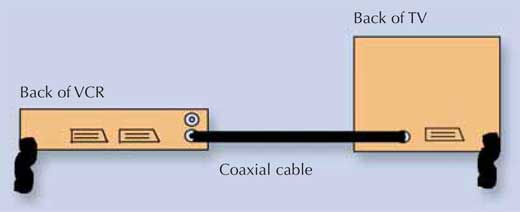
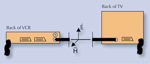
A VCR can transmit sound and images to a TV via either the SCART cable or the classic coaxial antenna cable. When transmitting via the coaxial cable, the VCR emulates a TV transmitter: in other words, the receiver doesn’t know whether it is receiving a programme transmitted by a distant, normal transmitter or by the nearer VCR. The VCR generates a radio signal that reaches the TV via the coaxial cable. If we cut the cable, and connect the pieces of cable to two antennae, the TV will receive the audio and video signals transmitted by the VCR without any physical connection: we have achieved radio transmission. The signal transmitted is very weak, so the two antennae can be separated by only a few metres.
The following instructions should be suitable for all teachers, including those who are unfamiliar with electrical equipment. A Microsoft PowerPoint presentationw2 and a short video clipw3 are available online.
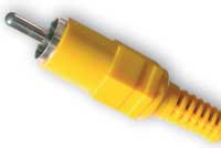
Remove the two pieces of the new coaxial cable from the TV and VCR and remove the external and internal insulating material along a length of about 20-30 cm (this length is not critical).
If the experiment is performed outdoors or if the classroom is close to a TV transmitter, the TV may receive signals other than those from the VCR. In this case, re-tune both the TV and the VCR. First, search for a channel on which the TV receives no signal. Then tune the output channel of the VCR to the same channel. If necessary, consult the instruction manuals. Alternatively, try the experiment in another room where the interference may be less.
Unauthorised radio transmission is strictly prohibited. Do not interpose devices such as amplifiers between the VCR and the transmitting antenna.
The simple experiment described here demonstrates the propagation of electromagnetic waves in air and, by placing the two antennae on either side of an obstruction (e.g. a book, a piece of aluminium foil or a wall), can be used to show how the waves penetrate objects.
The teacher can also demonstrate the polarisation of the waves by placing a metal grid between the two antennae. The waves cannot pass through the grid if the rods of the grid are parallel to the electric field vector (E in the figure above). However, the grid is penetrable if the rods are at right angles to the electric field vector.
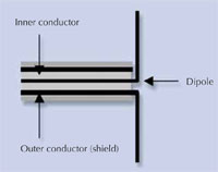
Radio transmission occurs when energy is carried by electromagnetic waves. This transmission may be achieved simply by applying a high-frequency voltage to a dipole antenna with a total length similar to the wavelength of the electromagnetic waves.
VCRs generate ultra-high frequency (UHF) signals in the 470-862 MHz range; the exact frequency range depends on the European channel selectedw4. Since the wavelength (l) is related to the frequency (f) by the simple formula l = c/f (where c is the speed of light), the wavelength is in the range of 0.35-0.63 m, requiring a small antenna.
Electromagnetic waves generated by the dipole antenna are linearly polarised. The direction of the electric field (E in the figure above) is parallel to the antenna.
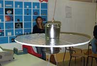
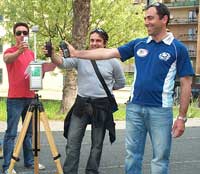
The schools involved in this project recently organised a public event about the scientific, technical and social aspects of electromagnetic fields. During this event, seven projects were presented to visitors by the school students.
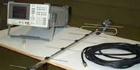
The event was supported by Consorzio Elettra 2000w5, which organised a national contest – Campi Elettromagnetici e Società (Electromagnetic Fields and Society) – to stimulate secondary schools to develop projects to communicate the social aspects of electromagnetism. Consorzio Elettra 2000 provided the instruments necessary to measure the electric and magnetic fields. More details about this event are available onlinew6.
The seven school projects also took part in the national contest, with one of them winning a trip to Rome.
This article describes an easy to prepare and interesting physics experiment to show wireless electromagnetism. Both the simple theoretical and practical aspects are covered.
Myrto Pouangare, Cyprus
How to Make a Simple Radiotransmission by Using a Videorecorder and a TV-receiver (Ppt)
Download this article as a PDF